How meters measure gas
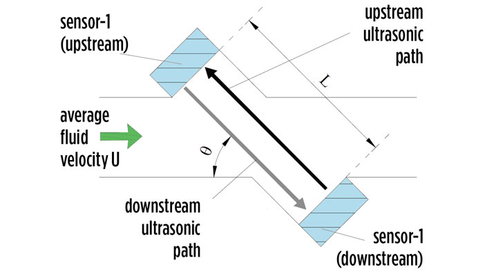
The ultrasonic meter measurement does not include mechanical or moving parts. (Image courtesy of Cavagna North America)
In the propane industry, the topic of gas meters presents challenges.
Meter reading, calculating volume, the different inlet pressures, indexes and difficulty understanding the meters are all concerns. I am referring to the more traditional diaphragm (positive displacement) meter that has been a workhorse for decades.
Diaphragm meters have measurement compartments that alternately fill and empty as the meter operates. As each compartment fills and empties its volume, and by applying the proper gear ratio, the meter reads the gas volume in cubic feet or cubic meters.
Components of a diaphragm meter:
- A body to contain the gas pressure and two compartments that measure the gas.
- Diaphragms that move as the gas pressure fluctuates to fill those compartments.
- Valves and seats that control the flow of gas into each compartment.
- Linkage connecting the diaphragm with the valves and index.
- The index, which registers the number of revolutions to calculate a measurement.
Each cycle of the diaphragm displaces a fixed volume of gas, so when one compartment empties, the other is filling. This provides a consistent flow of gas to the meter outlet. When there is a flow of gas downstream, the pressure drop allows the processes to start. A series of rods and gears measures the gas volume, which is where the reference to mechanical meters comes from. Moving parts create friction and wear, which is why mechanical meters are checked to ensure the tolerances are maintained for accurate volume readings.
Technology changes
Ultrasonic meters use a static measurement technology that provides a more precise measurement over time. The ultrasonic meter measurement does not include mechanical or moving parts, so there is no friction or wear over time. As flow passes through the meter from demand downstream, it passes through a flow tube with a known diameter. The ultrasonic sensor is positioned in this tube to measure the flow of gas.
Components of an ultrasonic meter:
- A body to contain the flow of gas that is measured.
- Internal shut-off valve at the inlet.
- A flow tube.
- Two ultrasonic sensors.
In the figure, sensor 1 is placed at an angle in the direction (upstream) of the flow and sensor 2 at an angle (downstream) of the flow within a tube of known diameter.
Sensor 1 (upstream) sends an ultrasonic pulse downstream across the tube to the opposite sensor 2 (downstream transducer). Sensor 2 (downstream) sends an ultrasonic signal upstream to sensor 1. The electronic control board measures the amount of time it takes each signal to complete its path.
If you were paddling a canoe across a river, it would take longer to cross against the current than with it. This is the same principle used in an ultrasonic meter. It takes the signal a longer time against the flow than with the flow.
This time difference is directly related to the gas flow rate (velocity), and since we know the diameter of the flow tube, the measurement is precise. As the flow increases, it simply changes the amount of time the signal needs to complete its path. The sensor has a maximum allowable pressure rating to operate and does not require the changing of gears. If there is no flow, the signal time of the path coming from sensor 1 and sensor 2 will be the same. The temperature of the gas can affect the speed and, therefore, the sensor measures the temperature of the gas, and the meter compensates that measured volume to 60 degrees F, providing a volume of gas that has been temperature compensated.
The volume measurements send electronically from the meter to a portal, which allows the user to receive the data remotely. This saves time compared to physically reading meters. The data also can be evaluated to determine the health of the meter and volume of gas flowing.
Read more:
- Understanding the heart of the propane system
- Understand automatic changeover regulators
- Developing new safety standards
Randy Warner is product safety manager for Cavagna North America. He can be reached at randywarner@us.cavagnagroup.com.
NOTE: The opinions and viewpoints expressed herein are solely the author’s and should in no way be interpreted as those of LP Gas magazine or any of its staff members.


